

Design engineers often face a difficult balancing act. You are tasked with pushing the boundaries of component complexity while simultaneously keeping production costs under control. When a project demands micromachining, extreme length-to-diameter ratios, or exceptionally smooth surface finishes, standard milling and turning methods reach their physical limits.
This is where advanced manufacturing steps in. Leveraging specialized CNC Swiss turning equipment allows you to achieve incredible precision for complex, small-diameter parts. However, a common misconception is that extreme precision must always command an astronomical premium.
By applying smart Design for Manufacturing (DFM) principles early in your Research and Development phase, you can optimize your part geometry specifically for the Swiss lathe. This engineering guide explores how subtle design adjustments prevent tool deflection, eliminate the need for secondary hand operations, and lower your total manufacturing investment while maintaining a zero-failure standard.
Understanding the Mechanics of the Swiss Lathe
To design effectively for this process, it helps to understand exactly how a Swiss-style machine operates differently from a conventional CNC lathe. In a traditional turning center, the bar stock is held firmly in a collet or chuck and rotates rapidly while the cutting tool moves along the length of the exposed material. If the part is long and thin, the force of the cutting tool causes the metal bar to flex or deflect, which ruins the dimensional accuracy of your part.
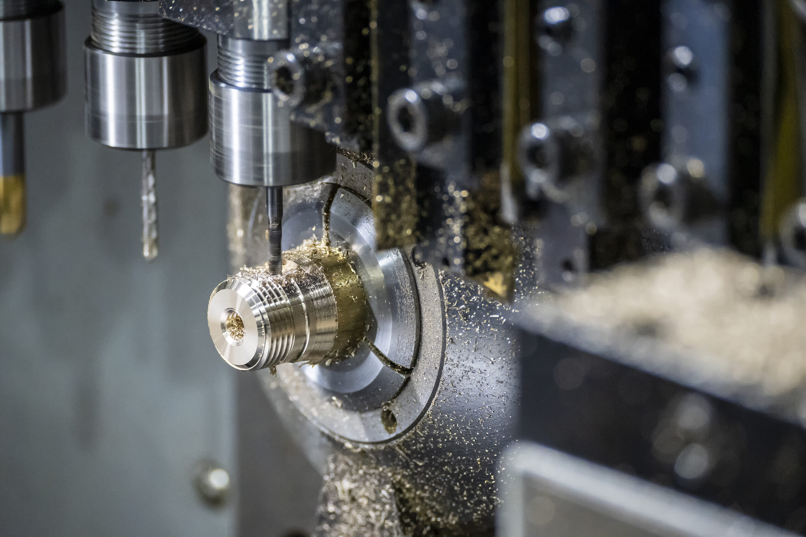
A Swiss lathe completely flips this mechanism. The raw bar stock is held securely inside the machine and passes through a rigid guide bushing. The cutting tools are positioned immediately adjacent to this guide bushing, usually within mere thousandths of an inch. Instead of the tool traveling down a long, unsupported piece of metal, the bar stock itself feeds forward out of the guide bushing as the tool cuts.
Because the material is supported by the guide bushing right at the point of cutting pressure, deflection is virtually eliminated. This unique mechanical advantage is what allows a high-capability precision machining company to hold an incredibly tight tolerance on parts with high length-to-diameter ratios. When you design components with these specific mechanical boundaries in mind, you unlock massive cost efficiencies.
Strategic DFM Principles for Precision Machining
Optimizing your component geometry for the Swiss process requires a deep understanding of tool paths, material behavior, and machine cycle times. Making small, intentional changes on your print can significantly reduce machining complexity.
Threading and Custom Tooling Adjustments
When designing threaded features, engineers often specify threads that run completely flush against a square shoulder. While this looks clean on a 3D CAD model, it introduces significant manufacturing challenges on the shop floor. To cut a thread all the way to a flat shoulder, the machine tool must stop abruptly or utilize specialized single-point threading tools that increase cycle times.
A more efficient alternative is to design a small thread relief undercut at the base of the shoulder. This undercut gives the threading tool a safe zone to exit the cut cleanly without colliding with the shoulder face. Additionally, whenever possible, you should standardize your thread sizes to match common, off-the-shelf tap and die dimensions. Specifying a non-standard or highly customized thread pitch forces the machine shop to procure custom tooling, which adds unnecessary cost and lead time to your initial production run.
Radii and Fillets vs. Sharp Inside Corners
Perfectly sharp 90-degree inside corners are another common element that drives up production costs. Cutting tools are inherently round, meaning a spinning endmill or turning insert will naturally leave behind a small radius in an inside corner. To achieve a perfectly crisp, sharp internal corner, the machinist must use extremely small tools or utilize secondary operations like Electrical Discharge Machining (EDM).
You can easily avoid this expense by designing generous internal radii into your corners. As a general rule, try to make the internal radius at least 10 percent larger than the radius of the cutting tool that will form it. This extra clearance allows the tool to transition smoothly through the corner without rubbing or stalling, which reduces tool wear, prevents tool breakage, and yields a superior surface finish.
Optimizing Wall Thickness and Aspect Ratios
The elimination of part deflection means Swiss machines can produce incredibly thin-walled components. However, there are still physical limits to what raw material can withstand. If an internal boring operation happens concurrently with an external turning operation on a part with extremely thin walls, the radial forces can stress the metal, resulting in microscopic distortions or roundness errors.
To maintain a highly repeatable tight tolerance, aim to keep your wall thicknesses above a minimum threshold of 0.015 inches whenever the application permits. If your design requires a deeply bored internal cavity, try to avoid extreme depth-to-diameter ratios. Deep holes require long, slender boring bars that are prone to vibration, which can negatively impact internal surface finishes and force the machine to run at much slower feed rates.
Eliminating Secondary Operations Through Single-Setup Machining
One of the greatest financial drains in precision manufacturing is part handling. Every time a component must be stopped, removed from a machine, deburred by hand, and loaded into a second piece of equipment, the risk of dimensional variation increases, and labor costs climb.
Modern Swiss machines feature highly advanced sub-spindles and live tooling stations. This means the machine can perform complex back-working operations, cross-drilling, milling, and slotting all within the exact same automated setup.
When you partner with an experienced contract manufacturer providing comprehensive precision machining services, their application engineers will review your print to maximize this single-setup capability. For example, if your part requires an off-center hole or a flat notch milled into the side, designing the feature so it can be reached by standard live tools eliminates a secondary milling setup entirely. Designing parts that fall cleanly off the machine fully completed ensures maximum consistency and the most efficient use of your production budget.
Selecting the Right Materials for Precision Turning
Material selection plays a massive role in both the performance of your final component and the ease with which it can be machined. Choosing a metal or polymer that aligns well with Swiss tooling dynamics can drastically lower your production costs.
- Free-Machining Metals: Materials like Stainless Steel 303, Brass, or 12L14 steel offer excellent chip formation. This maximizes tool life and permits fast cycle times for high-precision components.
- Tough Alloys: Materials like Stainless Steel 316 or Titanium are highly valued for aerospace and medical applications but are prone to work-hardening. They require rigid setups and careful DFM to prevent tool deflection.
- Engineered Polymers: Plastics like PEEK, PTFE, and Delrin offer low mass and high chemical resistance. However, they require exceptionally sharp tooling and precise thermal management to prevent dimensional drifting during long runs.
By consulting with your manufacturing partner during the early design stages, you can often identify alternative material grades that offer the exact same mechanical properties but feature vastly superior machinability ratings.
Choosing an Investment Partner for High-Stakes Components
When you are sourcing complex components for critical applications in the medical device, aerospace, or electronics sectors, you cannot afford to treat your supplier as a simple transactional vendor. Supply chains are filled with stories of low-bid shops that promised the world, only to deliver batches of failing parts with slipping lead times because they lacked the technical depth to handle demanding tolerances.
Real efficiency is found by working with an invested engineering partner who takes the time to thoroughly analyze your drawings before the first chips are even made. This collaborative approach protects your pipeline from unexpected delays and ensures your critical assemblies function flawlessly from the very first delivery.
Optimize Your Next Component Run
If you are currently developing a high-precision component or looking to optimize an existing design for long-term production stability, our engineering team is ready to assist. We are obsessed with the details from initial communication to delivery of the final product, helping you achieve zero-failure reliability without unnecessary manufacturing costs.
To review your project blueprints with our technical team or to request an engineering consultation, please reach out to us directly.
- Submit Your Prints: Lakeview Precision Contact Page
Key Takeaways
- Guide Bushing Support: CNC Swiss machines eliminate part deflection by supporting the raw bar stock right next to the cutting tool, making them ideal for long, thin, precise components.
- Smart Geometry Lowers Cost: Adding thread reliefs and generous internal corner radii prevents tool breakage and eliminates costly secondary operations.
- Utilize Live Tooling: Designing features that can be machined in a single setup using live tools reduces manual handling and protects part quality.
- Early DFM Collaboration: Partnering with an expert manufacturing provider during the R&D phase allows you to discover cost-saving design opportunities before finalizing your production prints.