

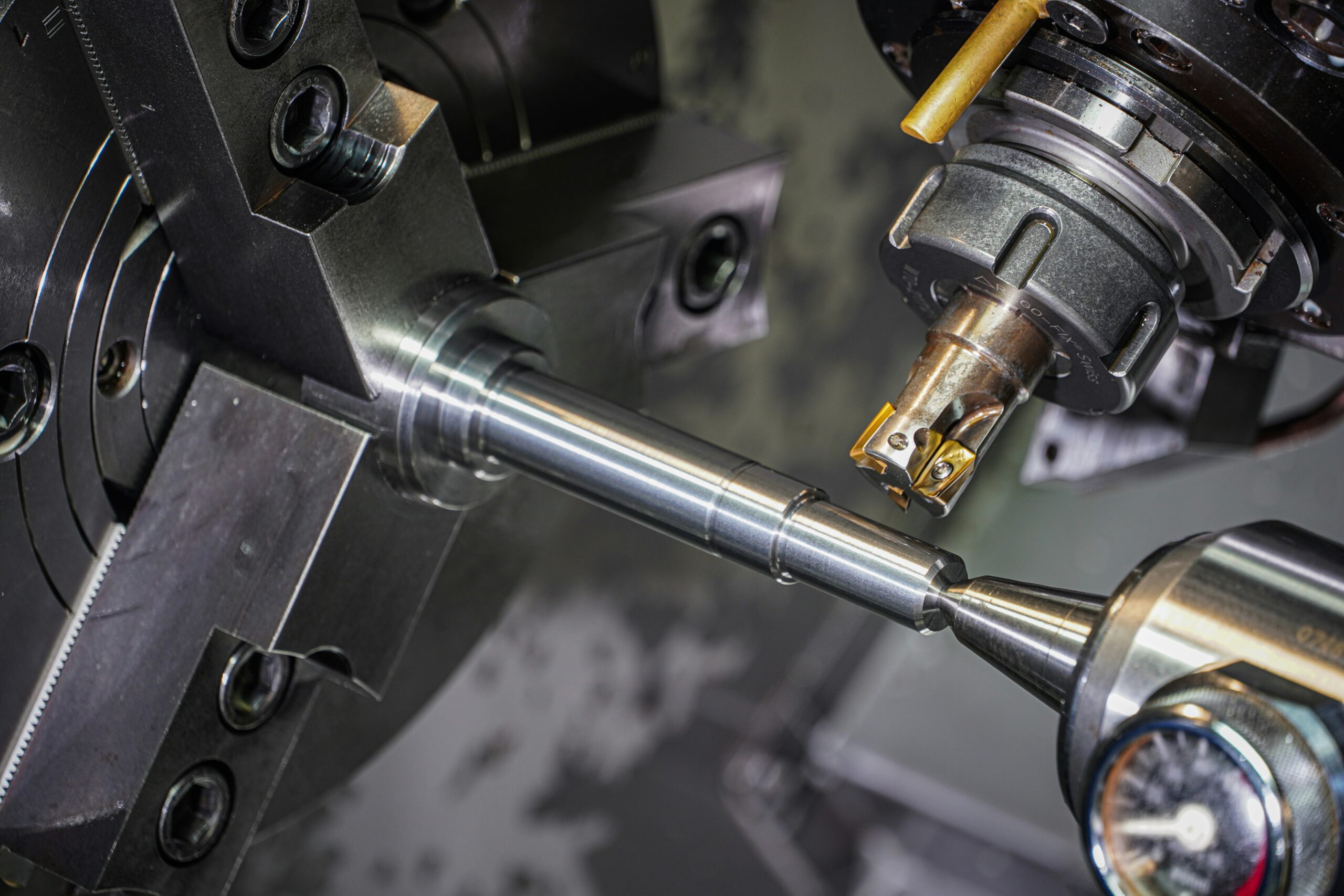
Defects in high-stakes component manufacturing jeopardize product performance, regulatory validation, and commercial launch schedules. For design engineers in the medical device, aerospace, and electronics sectors, a design for manufacturability (DFM) review represents the critical boundary between an optimized production run and a catastrophic failure. Failing to account for structural stress, cutting tool access, or material behavior during the initial drawing phase leads to excessive scrap rates and unworkable components. High-risk assemblies require an advanced understanding of how geometry interacts with live tooling during production.
Transitioning a complex component from a CAD model into physical reality requires more than basic machining capabilities. It demands a deliberate alignment between the engineering print and the physical constraints of production machinery. When structural dimensions demand a tight tolerance of 0.0002 inches, standard milling and turning methods introduce unacceptable geometric errors. A comprehensive DFM strategy addresses these manufacturing realities before a single piece of bar stock enters the machine spindle, ensuring that every feature aligns perfectly with your production intent.
Material Behavior and Stress Management in Complex Alloys
Machinability and Thermal Realities of Exotic Metals
Selecting the appropriate material involves balancing physical performance attributes with the structural realities of the cutting process. High-strength materials common in medical implants and aerospace valves, such as Titanium Grade 5 or 17-4 PH stainless steel, exhibit significant work-hardening tendencies under standard cutting forces. If a component drawing specifies sharp internal corners or thin walls without accounting for the structural memory of the metal, the material deforms as stress relieves during machining.
Thermal accumulation represents another critical factor when executing a high-risk tight tolerance machining program. Exotic alloys display lower thermal conductivity than standard carbon steels or aluminum, meaning the heat generated during chip formation transfers directly into the cutting tool and workpiece. This localized heat buildup causes microscopic dimensional expansion during the cut. Engineers must design component geometries that allow for adequate coolant access and efficient chip evacuation to maintain absolute dimensional stability across thousands of consecutive cycles.
Grain Direction and Structural Stability
Bar stock possesses a distinct grain structure resulting from the cold-drawing or rolling processes utilized during material production. When engineers specify deep, narrow grooves or highly asymmetrical pockets, machining across these inherent grain lines alters the internal equilibrium of the metal. The material naturally warps to find a new equilibrium state once released from the workholding fixture. Design profiles must accommodate raw material grain orientation, distributing machining forces evenly to eliminate post-production distortion.
Optimizing Profiles for Advanced CNC Swiss Turning
Slenderness Ratios and Deflection Mitigation
Long, slender components designed for medical instruments or miniature electronic connectors present severe deflection risks on standard lathes. Traditional turning centers support the workpiece at one or both ends, leaving the middle section vulnerable to the pushing force of the cutting tool. This structural setup causes part deflection, resulting in a tapered component that fails concentricity inspections.
Utilizing specialized CNC Swiss turning services resolves this issue by supporting the raw stock through a rigid guide bushing immediately adjacent to the cutting tool. The machining forces are applied fractions of an inch from the support point, eliminating material flexing entirely. Engineers can maximize this capability by designing uniform outer diameters and avoiding abrupt step-downs that require specialized, non-standard guide bushing geometries.
Guide Bushing Clearance and Feature Placement
Designing for Swiss-type manufacturing requires careful consideration of feature placement relative to the face of the guide bushing. Sub-spindle operations handle back-working features simultaneously while the main spindle executes primary operations, maximizing throughput and geometric uniformity. Placing critical cross-holes, threads, or milled flats too close to transitions can limit tool clearance, forcing manual interventions that disrupt structural consistency. Designing parts with adequate transition zones allows the machine tools to access features cleanly without compromising cycle efficiency.
Micro-Burr Prevention and Edge Conditioning Strategies
Tool Exit Paths and Burr Minimization
Burrs represent an inherent reality of subtractive manufacturing, occurring whenever a cutting edge exits a metal surface. In high-risk electronics or medical applications, a loose microscopic burr can migrate into sensitive circuitry or bloodstreams, causing system failure or patient harm. While secondary deburring operations exist, they introduce human variable risks and dimensional variance. The most reliable method to achieve pristine edges is preventing burr formation through correct geometric design.
Engineers minimize exit burrs by avoiding intersecting holes that cross at acute angles. When a cross-hole exits into a primary bore at an angle other than 90 degrees, the cutting tool creates an ultra-thin feather edge that naturally rolls into a heavy burr. Designing perpendicular intersections ensures the cutting tool cuts cleanly through the material wall, leaving a manageable, consistent edge that can be automatically radiused during the primary machining cycle.
Specifying Measurable Radii Over Sharp Edges
Drawings that call for sharp edges or break all corners without specifying an exact dimensional range present clear quality tracking challenges for inspection departments. A perfectly sharp edge is a mathematical abstraction that cannot be consistently machined or verified. Instead, specify a controlled radius range, such as 0.003 to 0.005 inches, that allows the machinist to program a precise toolpath using standard corner-turning inserts. This approach produces repeatable edge profiles while ensuring your manufacturing partner can verify compliance using optical metrology systems.
Threading and Tapping Geometry Realities
Thread Relief and Blind Hole Constraints
Threading down to a sharp shoulder or tapping to the absolute bottom of a blind hole introduces unnecessary manufacturing hazards. Cutting taps and thread-rolling heads require a lead section to engage the material properly, meaning the first few threads will not achieve full profile depth. Forcing a tool to cut full-depth threads against a bottom surface increases tool breakage risks and creates packed nests of chips that damage internal finishes.
Incorporate a thread relief groove at the base of external shoulders to provide a clean exit zone for the threading tool. For internal blind holes, extend the drilled depth beyond the required thread depth by a distance equal to at least three full thread pitches. This clearance zone provides sufficient space for chip accumulation and tool overtravel, guaranteeing clean, fully formed threads without risking a broken tap inside a nearly completed component.
Pitch and Diameter Ratios in Miniature Components
Micro-miniature components for electronic housings require exceptionally fine pitch threads machined into temperamental alloys. As thread pitch decreases, the allowable margin for error shrinks rapidly, requiring precise control over the pre-tap drill diameter. Designers must avoid pairing extremely fine threads with ultra-deep holes, as long, thin taps experience high torsional stress and deflect easily, leading to pitch diameter errors that fail thread plug gauge inspections.
About the Author
Written by the Lakeview Precision engineering team, CNC Swiss turning specialists serving medical, aerospace, and electronics manufacturers from South Elgin, Illinois. Our team possesses decades of combined experience executing complex manufacturing programs, maintaining a reputation for solving difficult geometric challenges and delivering zero-failure components across the Midwest manufacturing corridor.
With over 40 years of precision manufacturing experience, Lakeview Precision serves as an invested engineering partner holding tight tolerance specifications down to 0.0002 inches for the medical, aerospace, and electronics industries. Our South Elgin, Illinois facility is equipped to conduct thorough design for manufacturability reviews that eliminate supply chain variables and protect your production pipeline.
Contact our applications engineering team today to review your component prints and optimize your design for production: https://www.lakeviewprecision.com/contact/
Key Takeaways
- Address Material Integrity Early: High-strength alloys warp during machining if internal stresses are not balanced through symmetrical geometry and proper grain alignment.
- Leverage Swiss Capabilities: Maximize concentricity on long, slender parts by designing geometries optimized for guide-bushing support and dual-spindle operations.
- Eliminate Micro-Burr Risks: Design perpendicular intersecting holes to prevent the formation of unmanageable feather edges that require hazardous manual deburring.
- Provide Thread Tooling Clearances: Always include thread relief grooves and deep blind hole extensions to prevent tool breakage and guarantee clean thread profiles.
- Partner for DFM Insights: Engage your precision machining source during the initial design phase to match your print specifications with optimal machine capabilities.